Mechanical Information
Height Profile
The figure below illustrates the height profile of the Ethernet FMC. Note that the quad RJ45 connector with integrated magnetics has a maximum height of 13.84mm; this limits the Ethernet FMC for mating only with FMC connectors that are located close to the edge of the carrier board. In other words, the Ethernet FMC must be able to extend over the edge of the carrier board to allow for clearance of the RJ45 connector. All of the Xilinx development boards provide this level of clearance and are designed with the FMC connectors in close proximity to the edge of the board.

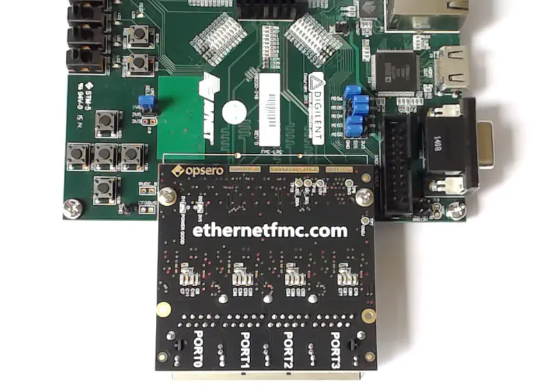
The figure below displays an example of a carrier board with an FMC connector that is located in close proximity to the board edge. The Ethernet FMC is limited to mating with this type of carrier board only.

Dimensions
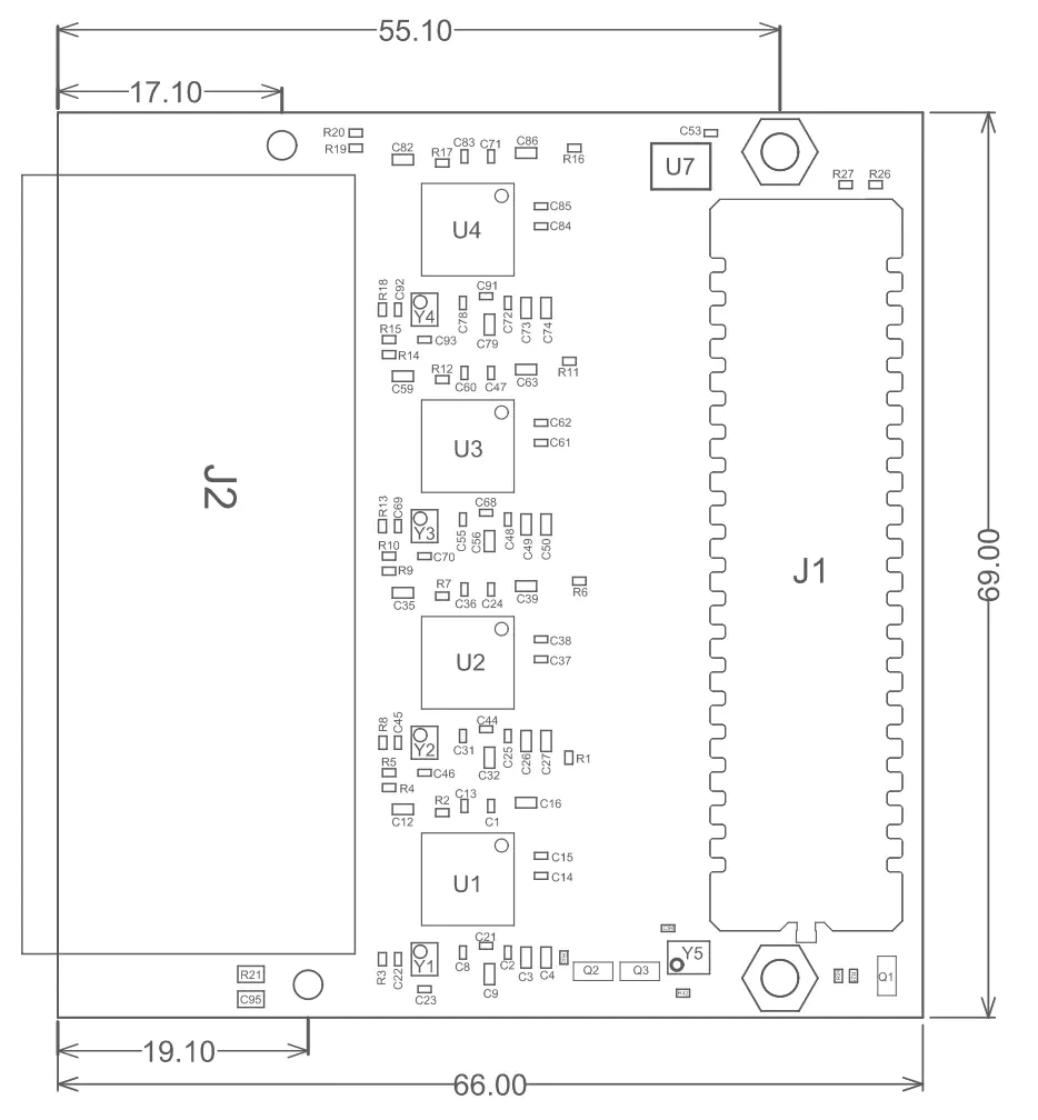
The mechanical dimensions of the Ethernet FMC are illustrated in the figure below. All dimensions are in millimeters (mm).
The assembly drawings are also available as PDF files that you can download at the provided links.

- Ethernet FMC Rev-D Assembly Drawing
- Ethernet FMC Rev-E Assembly Drawing
- Ethernet FMC Rev-F Assembly Drawing
3D Model
The 3D model of the board is available as a STEP file at the links below:
Mezzanine fastening hardware
For mechanical fastening of the mezzanine card to the carrier board, the Ethernet FMC comes with 2x hex standoffs. It is recommended to use a machine screw on each of these standoffs to fix the mezzanine card to the carrier board.
The hex standoff and machine screw part numbers are listed below:
Hex standoff, Thread M2.5 x 0.45, Brass, Board-to-board length 10mm
Part number: V6516C
Manufacturer: AssmannMachine screw, Thread M2.5 x 0.45, Length (below head) 4mm, Stainless steel, Phillips head
Part number: 90116A105
Supplier: McMaster-Carr