RGMII Interface Timing Considerations
RGMII Timing Basics
The RGMII interface is the physical connection between the Ethernet PHY and the Ethernet MAC. If you are using the Ethernet FMC , the PHY is the Marvell 88E151x , and the Ethernet MAC is inside the FPGA. The RGMII interface is a dual data rate (DDR) interface that consists of a transmit path, from FPGA to PHY, and a receive path, from PHY to FPGA. Both paths have an independent clock, 4 data signals and a control signal.
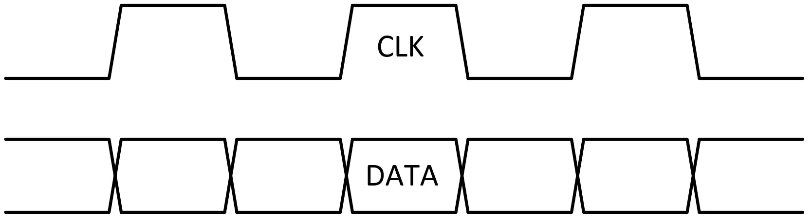
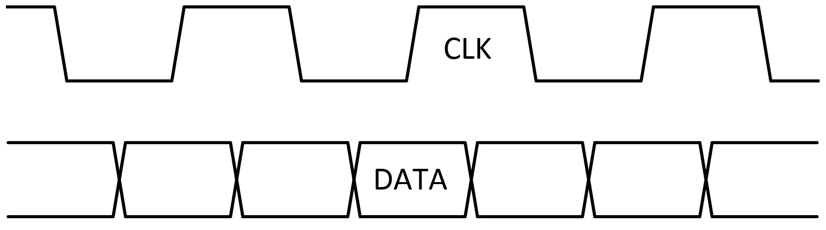
The RGMII standard specifies that data and clock be output simultaneously (ie. without any skew on the clock), as shown in the left-side image below. For proper sampling of the data signals at the receiver side, the RGMII standard specifies that skew be added to the clock signal, either by the PCB traces, or by the receiver itself (on the TX path, the receiver is the PHY, whereas on the RX path, the receiver is the FPGA). The right-side image below shows the clock and data signals after clock skew has been added.
If you are experiencing one of the following problems, then you probably have an issue with your RGMII interface:
- Ethernet port is transmitting but not receiving
- Ethernet port is receiving but not transmitting
- Ethernet port is working at 10Mbps and 100Mbps but unable to work at 1Gbps
RGMII Interface without clock skew
The RGMII standard specifies clock and data signals to be output with no skew, ie. the
clock edges are aligned with the data edges. This is not ideal for the receiver’s sampling
circuit, but it greatly simplifies the transmitter circuit.
RGMII Interface with clock skew
RGMII clock and data signals as they must be presented to the receiving circuit for
optimal sampling. The clock skew has been added by the PCB trace or the receiving device.
Adding the clock skew
In an FPGA based system, there are three stages where the required skew (ie. delay) can be added to the TX and RX clock signals. The first stage is in the FPGA, the second stage is on the PCB traces (ie. with longer clock traces than the data traces) and the third stage is in the PHY. In an optimal RGMII interface, the skew is added at only one stage in the TX and RX path, and the other two delay stages are disabled or not implemented.
Clock skew stages in the RGMII interface
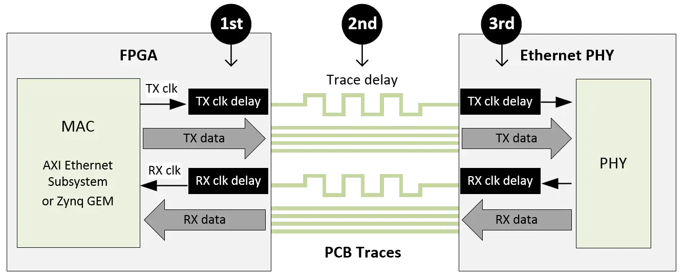
The skew of the TX and RX clocks can be managed independently, it does not have to be implemented at the same stage on each path, but it must be implemented somewhere on each path. So it is critical to understand each of the delay stages in your target system in order to ensure that the clocks in your RGMII interface are properly skewed. We will now discuss each skew stage and the various ways to enable or disable them.
Stage 1: FPGA
Whether or not the clock skew is implemented in the FPGA, and how it is implemented depends on the IP that you are using to implement the MAC.
AXI Ethernet Subsystem
TX clock skew: YES
The
AMD Xilinx AXI Ethernet Subsystem IP
IP core is designed to output a TX clock with skew, and there is
no option in the Vivado GUI to disable this skew. It does this by clock forwarding a clock
with a 90 degrees phase shift with respect to the clock that is used to output the data signals.
In summary, when using AXI Ethernet Subsystem, you must disable TX clock skew in the PHY and
ensure that there is no skew added by the TX clock trace on the PCB.
RX clock skew: NO
The AXI Ethernet Subsystem IP core does not add skew to the RX clock, therefore the skew must
be added by either the PHY or the PCB trace.
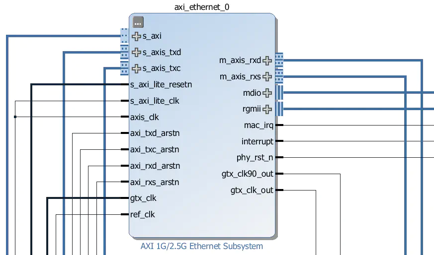
For more detailed information concerning the TX and RX clock skew in the AXI Ethernet Subsystem, you must refer to the product guide for the Tri-mode Ethernet MAC IP, which is wrapped by AMD Xilinx AXI Ethernet Subsystem IP .
GMII-to-RGMII
(for connecting the Zynq GEM via EMIO)
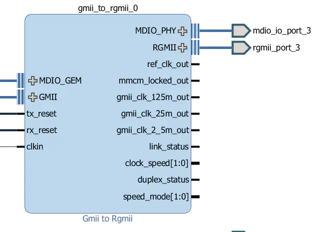
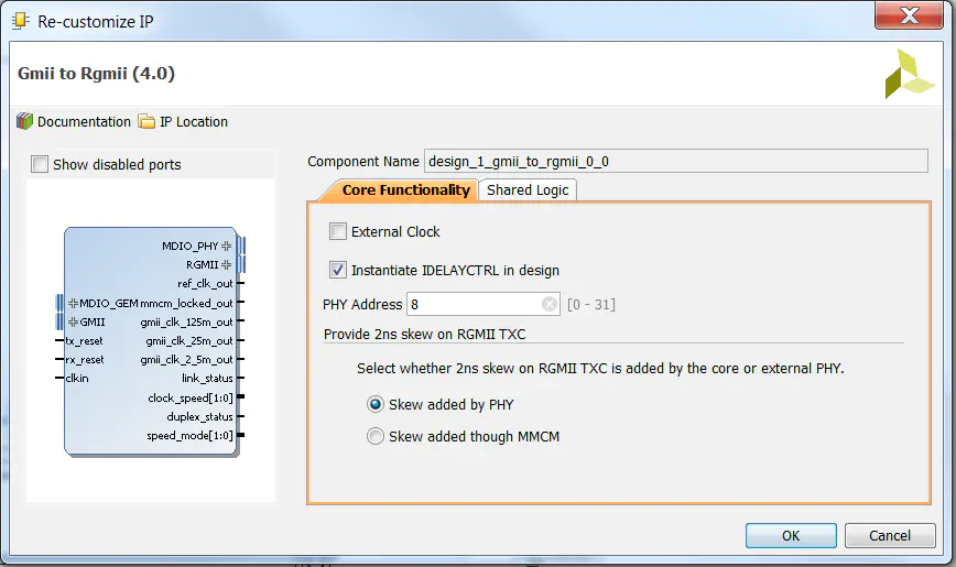
TX clock skew: OPTIONAL
The
AMD Xilinx GMII-to-RGMII IP
core has an option to add 2ns of skew to the TX clock. This option can be
accessed in the Vivado GUI through the option “Skew added by PHY” (see below image). When
this option is ticked, the core will output the TX clock without skew. When unticked, the core
will output the TX clock with 2ns of skew.
RX clock skew: NO
According to the
AMD Xilinx GMII-to-RGMII IP product guide
page 29, the GMII-to-RGMII core does not add skew
to the RX clock, so the skew must be added by the PHY or the PCB clock trace.
For more detailed information regarding the TX and RX clock skew in the GMII-to-RGMII core, please refer to the product guide.
Zynq GEM via MIO
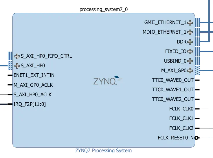
TX clock skew: NO
The Zynq GEMs do not add clock skew to the TX clock, therefore the skew must be added by the PHY
or the PCB trace.
RX clock skew: NO
The Zynq GEMs do not add clock skew to the RX clock, therefore the skew must be added by the PHY
or the PCB trace.
If you are using the Ethernet FMC , it is very unlikely that the Zynq MIO pins are routed to the FMC connector, but this case has been included here for completeness.
Stage 2: PCB
The Ethernet FMC has clock and data traces that are length matched between the FMC connector and the PHYs, therefore, no clock skew is added by the Ethernet FMC PCB traces. However, to get the complete picture, we must also consider the length of the traces on the FPGA board. Luckily, most FMC carriers (such as the ZedBoard and the AMD Xilinx ZC706 ) are designed with length matched traces between the FPGA and all of the FMC connector’s I/Os. Hence in most cases, when using the Ethernet FMC, you can expect the overall clock and data traces to be length matched all the way from the PHYs to the FPGA. As such, you must ensure that the clock skew is added by either the PHY or the FPGA.
Custom FPGA Boards
Although the PCB traces can be designed to implement the clock skew, in most cases this is the least ideal location to implement the skew, so most board designers will route RGMII clock and data traces that are length matched. That said, it is important to know if your PCB’s RGMII interface has been routed with clock skew so that you know how to appropriately configure the FPGA and PHYs – ask your board designer if you’re not sure. If your PCB has been routed with clock skew, then you must disable clock skew in both the FPGA and the PHY.
Stage 3: PHY
The Marvell Marvell 88E151x product brief Ethernet PHYs were designed with two internal delays which can be enabled to add skew to the incoming RGMII TX clock and the outgoing RGMII RX clock independently. The delay, regardless of link speed, is always 1.9ns. The delays are enabled or disabled by writing to a particular register in the PHY, accessed over the MDIO bus. How this is handled depends on whether you are running Linux or a stand-alone application.
Linux
In Linux applications, the simplest way to enable or disable the internal clock delays is through the device tree. The device tree will contain a section for each of your Ethernet interfaces and it should look similar to the one shown to the right.
To enable or disable the internal clock delays, we specify a particular value for the “phy-mode” parameter.
- Both internal delays DISABLED:
phy-mode = "rgmii"; - Both internal delays ENABLED:
phy-mode = "rgmii-id"; - Only RX internal delay ENABLED:
phy-mode = "rgmii-rxid"; - Only TX internal delay ENABLED:
phy-mode = "rgmii-txid";
&axi_ethernet_0 {
    local-mac-address = [00 0a 35 00 01 22];
    phy-handle = <&phy0>;
    xlnx,has-mdio = <0x1>;
    phy-mode = "rgmii";
    mdio {
        #address-cells = <1>;
        #size-cells = <0>;
        phy0: phy@0 {
            compatible = "marvell,88e1510";
            device_type = "ethernet-phy";
            reg = <0>;
        };
    };
};
Stand-alone
When using a standalone application, we have to perform the specific register writes over the MDIO bus in order to enable/disable the internal clock delays.
- The TX clock delay is enabled by setting bit 4 of register 21 of page 2.
- The RX clock delay is enabled by setting bit 5 of register 21 of page 2.
Below is an example of doing this for each of the 4 possible configurations. Note that we are using function calls to the AXI Ethernet Subsystem library; the names of the equivalent functions for the Zynq GEM will be slightly different.
#define PHY_ADDRESS                0   // Ethernet FMC PHY address
#define IEEE_CONTROL_REG_MAC       21  // The register containing the TX/RX clock delay enables
#define IEEE_PAGE_ADDRESS_REGISTER 22  // For specifying the page number
#define IEEE_RGMII_TX_CLOCK_DELAYED_MASK 0x0010
#define IEEE_RGMII_RX_CLOCK_DELAYED_MASK 0x0020

u16 control;

// RGMII with both internal delays disabled
XAxiEthernet_PhyWrite(xaxiemacp, PHY_ADDRESS, IEEE_PAGE_ADDRESS_REGISTER, 2);
XAxiEthernet_PhyRead(xaxiemacp, PHY_ADDRESS, IEEE_CONTROL_REG_MAC, &control);
control &= ~(IEEE_RGMII_TX_CLOCK_DELAYED_MASK | IEEE_RGMII_RX_CLOCK_DELAYED_MASK);
XAxiEthernet_PhyWrite(xaxiemacp, PHY_ADDRESS, IEEE_CONTROL_REG_MAC, control);

// RGMII with both internal delays enabled
XAxiEthernet_PhyWrite(xaxiemacp, PHY_ADDRESS, IEEE_PAGE_ADDRESS_REGISTER, 2);
XAxiEthernet_PhyRead(xaxiemacp, PHY_ADDRESS, IEEE_CONTROL_REG_MAC, &control);
control |= (IEEE_RGMII_TX_CLOCK_DELAYED_MASK | IEEE_RGMII_RX_CLOCK_DELAYED_MASK);
XAxiEthernet_PhyWrite(xaxiemacp, PHY_ADDRESS, IEEE_CONTROL_REG_MAC, control);

// RGMII with only RX internal delay enabled
XAxiEthernet_PhyWrite(xaxiemacp, PHY_ADDRESS, IEEE_PAGE_ADDRESS_REGISTER, 2);
XAxiEthernet_PhyRead(xaxiemacp, PHY_ADDRESS, IEEE_CONTROL_REG_MAC, &control);
control &= ~IEEE_RGMII_TX_CLOCK_DELAYED_MASK;
control |= IEEE_RGMII_RX_CLOCK_DELAYED_MASK;
XAxiEthernet_PhyWrite(xaxiemacp, PHY_ADDRESS, IEEE_CONTROL_REG_MAC, control);

// RGMII with only TX internal delay enabled
XAxiEthernet_PhyWrite(xaxiemacp, PHY_ADDRESS, IEEE_PAGE_ADDRESS_REGISTER, 2);
XAxiEthernet_PhyRead(xaxiemacp, PHY_ADDRESS, IEEE_CONTROL_REG_MAC, &control);
control |= IEEE_RGMII_TX_CLOCK_DELAYED_MASK;
control &= ~IEEE_RGMII_RX_CLOCK_DELAYED_MASK;
XAxiEthernet_PhyWrite(xaxiemacp, PHY_ADDRESS, IEEE_CONTROL_REG_MAC, control);
Case-by-case
In closing this section, we will list the required RGMII delay configuration for each of the possible use cases. As the majority of applications use length matched PCB traces, we will assume no clock skew is added by the PCB. Here are the required configurations for each of the three MAC options:
Case 1: Using AXI Ethernet Subsystem
- TX clock skew must be DISABLED in PHY (because the skew is implemented in the FPGA)
- RX clock skew must be ENABLED in the PHY
In Linux, use:
phy-mode = "rgmii-rxid";
In standalone applications, use the following code:
// RGMII with only RX internal delay enabled
XAxiEthernet_PhyWrite(xaxiemacp, PHY_ADDRESS, IEEE_PAGE_ADDRESS_REGISTER, 2);
XAxiEthernet_PhyRead(xaxiemacp, PHY_ADDRESS, IEEE_CONTROL_REG_MAC, &control);
control &= ~IEEE_RGMII_TX_CLOCK_DELAYED_MASK;
control |= IEEE_RGMII_RX_CLOCK_DELAYED_MASK;
XAxiEthernet_PhyWrite(xaxiemacp, PHY_ADDRESS, IEEE_CONTROL_REG_MAC, control);
Case 2: Using GMII-to-RGMII (Zynq GEM via EMIO)
When using GMII-to-RGMII, you have the choice of where to implement the TX clock skew, so there are two possibilities:
Option 1: TX clock skew ENABLED in FPGA
- TX clock skew must be DISABLED in the PHY
- RX clock skew must be ENABLED in the PHY
In Linux, use:
phy-mode = "rgmii-rxid";
In standalone applications, use the following code:
// RGMII with only RX internal delay enabled
XAxiEthernet_PhyWrite(xaxiemacp, PHY_ADDRESS, IEEE_PAGE_ADDRESS_REGISTER, 2);
XAxiEthernet_PhyRead(xaxiemacp, PHY_ADDRESS, IEEE_CONTROL_REG_MAC, &control);
control &= ~IEEE_RGMII_TX_CLOCK_DELAYED_MASK;
control |= IEEE_RGMII_RX_CLOCK_DELAYED_MASK;
XAxiEthernet_PhyWrite(xaxiemacp, PHY_ADDRESS, IEEE_CONTROL_REG_MAC, control);
Option 2: TX clock skew DISABLED in FPGA
- TX clock skew must be ENABLED in the PHY
- RX clock skew must be ENABLED in the PHY
In Linux, use:
phy-mode = "rgmii-id";
In standalone applications, use the following code:
// RGMII with both internal delays enabled
XAxiEthernet_PhyWrite(xaxiemacp, PHY_ADDRESS, IEEE_PAGE_ADDRESS_REGISTER, 2);
XAxiEthernet_PhyRead(xaxiemacp, PHY_ADDRESS, IEEE_CONTROL_REG_MAC, &control);
control |= (IEEE_RGMII_TX_CLOCK_DELAYED_MASK | IEEE_RGMII_RX_CLOCK_DELAYED_MASK);
XAxiEthernet_PhyWrite(xaxiemacp, PHY_ADDRESS, IEEE_CONTROL_REG_MAC, control);
Case 3: Using Zynq GEM via MIO
- TX clock skew must be ENABLED in the PHY
- RX clock skew must be ENABLED in the PHY
In Linux, use:
phy-mode = "rgmii-id";
In standalone applications, use the following code:
// RGMII with both internal delays enabled
XAxiEthernet_PhyWrite(xaxiemacp, PHY_ADDRESS, IEEE_PAGE_ADDRESS_REGISTER, 2);
XAxiEthernet_PhyRead(xaxiemacp, PHY_ADDRESS, IEEE_CONTROL_REG_MAC, &control);
control |= (IEEE_RGMII_TX_CLOCK_DELAYED_MASK | IEEE_RGMII_RX_CLOCK_DELAYED_MASK);
XAxiEthernet_PhyWrite(xaxiemacp, PHY_ADDRESS, IEEE_CONTROL_REG_MAC, control);